
If you hear people talking about Variable Frequency/Speed Drives (VFD/VSD), Inverters, or just Drives, it is basically the same thing – a device that can change both the frequency and voltage of the electricity supplied to a motor. Unlike a transformer, which can only change the voltage magnitude, a drive can manipulate both.
As the functioning of electrical motors relies heavily on the voltage and frequency of the power supply, we can alter how a motor behaves by placing a drive between the public grid and the motor. For AC induction motors, which are of a asynchronous type, the change in frequency will change the fundamental speed (the speed at 0% slip) meanwhile the change in voltage will change the magnetisation of the motor and hence impact the slip, making larger or smaller. For PM motors more advanced control techniques are needed, and it is further described in my previous blogpost here.
How Does a Drive Work?
The functionality of a drive is actually quite simple.
The first step is the convert the AC voltage from the public grid to a DC voltage which only have magnitude and no frequency. The magnitude of the DC voltage will approximately be the peak-peak value of the input AC voltage.
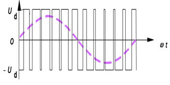
The next step is to output an AC voltage with a different frequency and magnitude. This is done by pulsating the voltage very quickly between on and off, and variant the percentage of time where the voltage is HIGH and the rest of the time the voltage will be LOW, this is called Pulse Width Modulation (PWM). By looking at this voltage, it is hard to see that it results in a discret sine curve, this can only be seen if the a low pass filter is applied to the voltage. There is an illustration of this in the figure below.
Losses in VFDs
However, VFDs aren’t perfectly efficient. Several factors contribute to losses within the drive. The primary losses come from:
- Conduction Losses: These occur when the switching transistors within the drive conduct current. The resistance of these transistors and the current flowing through them generates heat.
- Switching Losses: When the transistors switch states (on to off or off to on), there’s a brief period of high current flow, leading to energy dissipation.
- Capacitor Losses: VFDs use capacitors to filter and smooth the DC voltage. These capacitors have internal resistance and lose energy as heat during charging and discharging.
- Transformer Losses: (If the VFD includes a transformer) Core losses (hysteresis and eddy current losses) and copper losses occur in the transformer.
- Diode Losses: Diodes are used to rectify the DC voltage. They lose energy as heat during conduction.
Manufacturers continually work to minimize these losses through improved component design, better thermal management, and more efficient switching techniques. The specific amount of losses will vary depending on the VFD’s design, operating conditions (load, frequency), and quality of components. A well-designed, high-quality VFD will generally have a higher efficiency than a usually cheaper one, where less consideration is made during the design phase. Efficiency is often rated as a percentage – a higher percentage means less energy is wasted as heat.
Fundamental and Switching Frequencies
In this situation we are talking about two different frequencies, the fundamental frequency of the sine wave which is usually in the are of 5-500 Hz and the switching frequency which is the frequency of the PWM, this is usually in the range of 2-16 kHz.
A rule of thumb states that the switching frequency should be 21 times faster than the fundamental frequency, as it is required 21 points to properly describe a sine wave. It is also worth considering that the lower the switching frequency is the lower is the losses in the VFD, but it comes with a louder audible noise to the human ear, and vice versa for higher.
The high switching frequency doesn’t come without consequences, it has serval impact on the motor, firstly the rapid rise times and voltage peaks, will degrade the motor’s insulation system faster. It is therefore crucial to only use VFDs with motors which are designed for it, with an enhanced insulation system. The high frequencies also lead to small discharges in the bearing which degrades the lubrication which also lead to degradation of the grease and bearing lifetime. To mitogate this shaft grounding rings can be used to lead the current between the rotor and housing of the motor, limiting the discharge in the bearings. Additionally insulated or ceramic/hybrid bearings can be used, but these are usually 10 times more costly than regular bearings.
Electromagnetic Compatibility (EMC) and Harmonic Distortion in VFDs
VFDs can also introduce challenges related to electromagnetic interference (EMI) and harmonic distortion into electrical systems. Understanding these issues and how to mitigate them is crucial for reliable and compliant operation.
Electromagnetic Compatibility (EMC)
VFDs, with their switching transistors and rapidly changing currents, generate EMI. This EMI can manifest as radio frequency (RF) noise, conducted interference (noise on power lines), and radiated emissions. This interference can affect nearby equipment, such as sensitive control systems, communication devices, and other electrical systems.
The primary sources of EMI from a VFD are Switching Transients, the rapid switching of transistors creates short bursts of voltage and current, generating impulsive noise. To mitigate this VFDs have built-in EMC filters, which need to be carefully designed, and the general layout of the VFDs PBCA can also help reducing the generated noise.
Harmonic Distortion
VFDs can also introduce harmonic distortion into the electrical system. Harmonic currents are multiples of the fundamental frequency. If the harmonic currents are excessive, they can affect the grid voltage; a weak grid – characterized by a high impedance – can then impact other devices connected to the same grid. Harmonic currents are primarily generated by the non-linear nature of the VFD’s rectifier and the DC-link capacitor size. There are several ways to mitigate this, including utilizing a Power Factor Correction (PFC) circuit, either in a passive or active topology.
Compliance and Standards
Many industries have regulations regarding harmonic levels and EMC emissions. It’s important to ensure that the VFD and its application comply with relevant standards (e.g., IEEE 51, IEC 61000-3-2, and others).
Typical application where VFDs are used
There are various applications that benefit from the use of VFDs. Especially Fans and Pumps. But also for electrical vehicles it is crucial to use a VFD.
Fans and pumps have a cubic relation between rotational velocity and power draw, there are massive potential savings in energy by reducing the rotational velocity, when the need for air- and liquid-flow is low.
A small note regarding the switching frequency for the fan application. It is desired to aim for a low switching frequency at higher rotational velocities, where the power draw is at it’s highest and the fan is making a lot of noise by moving the air, so the switching noise is less pronounced and the energy saving are improved further.
What are in the scope for the future trends of VFDs
The VFD landscape is continuously evolving, with significant trends emerging. Key areas of focus include:
- Digitalization & IoT: VFDs are increasingly becoming connected devices, providing data and remote monitoring capabilities via the Internet of Things (IoT). This enables predictive maintenance, performance optimization, and streamlined energy management.
- Modular VFDs: Modular VFD designs offer flexibility and scalability, allowing for easy expansion of drive capacity without replacing the entire unit.
- Silicon Carbide and Gallium Nitride (SiC/GaN) Technology: These semiconductors offer higher switching speeds, lower losses, and increased efficiency, leading to smaller, lighter, and more powerful VFDs. They are especially crucial for applications requiring high frequency or high power.
- Increased Demand in Emerging Applications: Electric vehicles, robotics, and industrial automation are driving significant growth in VFD demand.
At last, thank you so much for your time reading my post I hope you enjoyed it! If you have any comments or just want to reach out, you can catch me here or on LinkedIn. If you want to receive more information about new articles, please don’t forget to sign up to my newsletter to recieve links to newest posts about electro magnetic topics. Don’t worry I will not send more than 1 mail per month.
Have a great day!
Kind regards,
Vlad